Anodizing Aluminum Parts
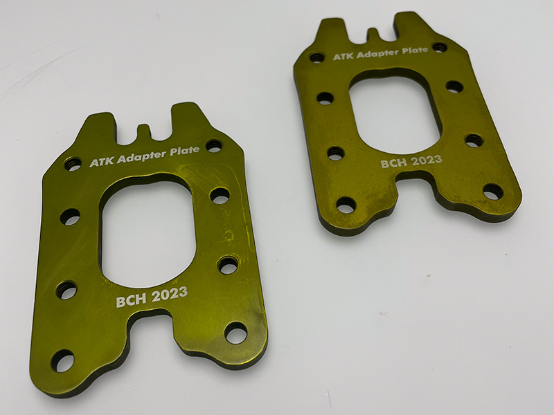
Last season, I picked up a pair of Scarpa F1 ski touring boots off a friend. I wanted to use these with my wider freeride skis for longer tours, but the boot sole length is significantly shorter. In fact, it was slightly too short for the adjustability range of the ATK Freeraider 14 bindings. The FR14s also have a quite large ramp delta (change in height between toe and heel). To correct both of these, I decided to make a toe spacer that provides a 6 mm decrease in ramp delta and allows the toepiece to be shifted 2 cm toward the tail of the ski. Often this is done with shim plates which can be made (e.g. from HDPE) or even purchased. But mostly, this project was done to try desiging and anodizing some aluminum parts.
What You Need
Part design files:
- Solidworks model (optional)
- DXF file for waterjet
Anodizing chemicals:
- Distilled water
- Sulfuric acid H2SO4 (oxalic acid also possible)
- Sodium hydroxide (for cleaning step, recommended)
- Nitric acid (for cleaning step, recommended)
- Phosphoric acid (for cleaning step, recommended)
- Anodizing dye (optional)
Anodizing supplies:
- DC power supply capable of around 1.5 A and 12 V
- Aluminum wire
The Design
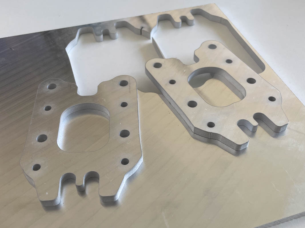
I first traced the bottom of the FR14 toepiece onto a sheet of graph paper. I then scanned this and made a simple design in Solidworks that shifts the holes 2 cm back. The toepiece may now be fastened to the adapter with M6 screws, and the adapter to the ski with the original screws. The parts ended up weighting about 48 g each. Note: in the rendering there are two sets of holes so that the toepiece can be mounted 1 cm or 2 cm back. In my final part, I kept only the set of holes for 2 cm.


Waterjet Cutting
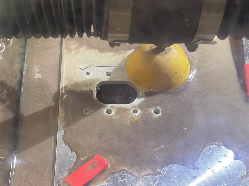
Next, I used the ProtoMAX waterjet cutter at my University’s maker-space to cut the adapter out of 6 mm 5058 Aluminum plate. This took about 12 minutes of cutting to yield the rough parts.
Anodizing Preparation
Like painting, the anodizing process is mostly determined by surface preparation. I chose to use the very thorough cleaning regime found in the useful paper by Donahue et al. [1]. It is very likely possible to avoid some of these unpleasant and costly solutions and use a different cleaning process. The goal is to have a perfectly clean and oil free surface. I decided to follow the paper because I had them on hand and access to a suitable work area. For the method from [1], the following solutions need to be prepared (I did the base, anodization, and sealing baths in 600 mL beakers and the acid clean in a short dish to reduce the amount of nitric acid requred). Take care with the acid solutions and work in a well ventilated space!
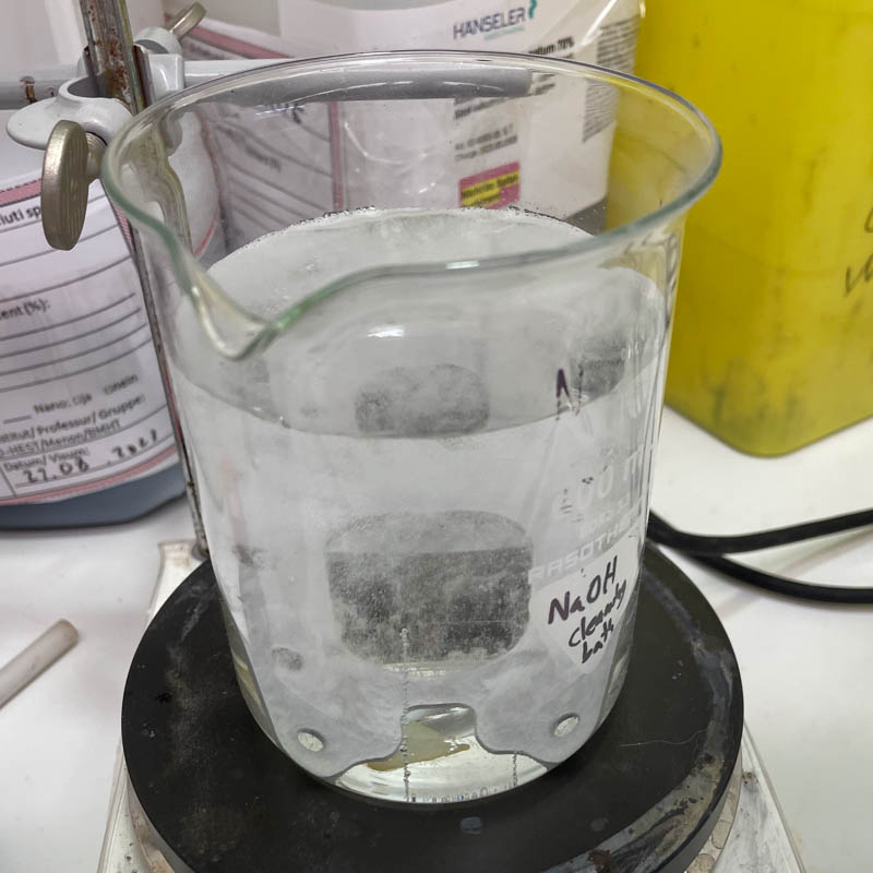
- Base cleaning bath - 10% w/v sodium hydroxide solution: 50 g NaOH in 500 mL H2O
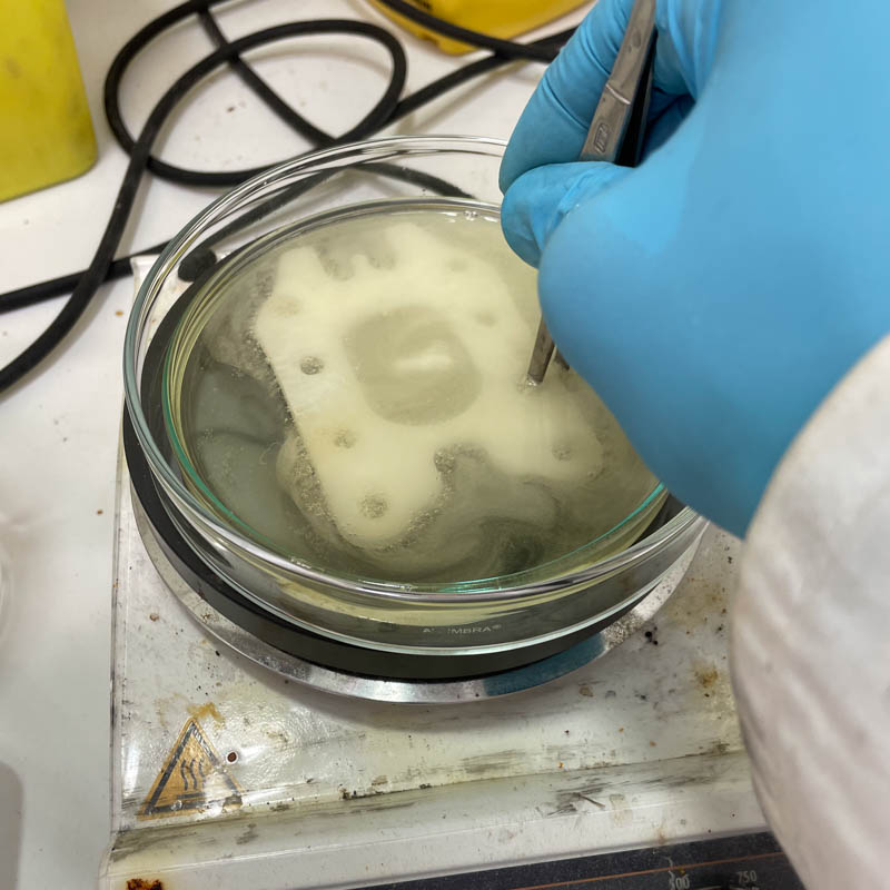
- Acid cleaning bath - 96.5% phosphoric acid 3.5% nitric acid solution: 77.2 mL H3PO4 mixed with 2.8 mL HNO3
The basic summary of the cleaning steps is:
- Wet sanding - I used a red Scotchbrite pad followed by unidirectional 600 grit wet sanding.
- Water rinse - 1 min under flowing tap water.
- Base bath - 1 min in the NaOH bath at 40°C (manipulate with tweezers).
- Water rinse - 1 min under flowing tap water.
- Acid clean - 1 min in the acid bath at 85°C (manipulate with tweezers).
- Distilled water rinse - 1 min under flowing tap water, then 1 min in distilled water.
- Air drying
Anodizing Process
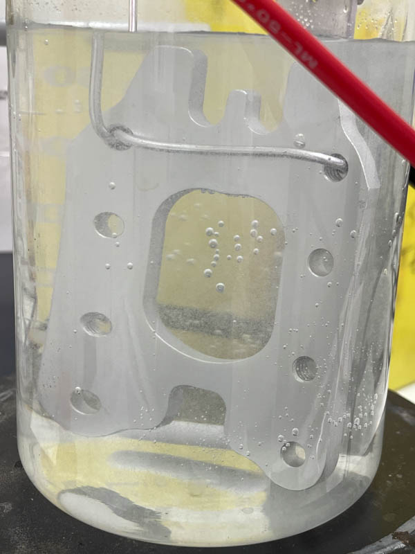
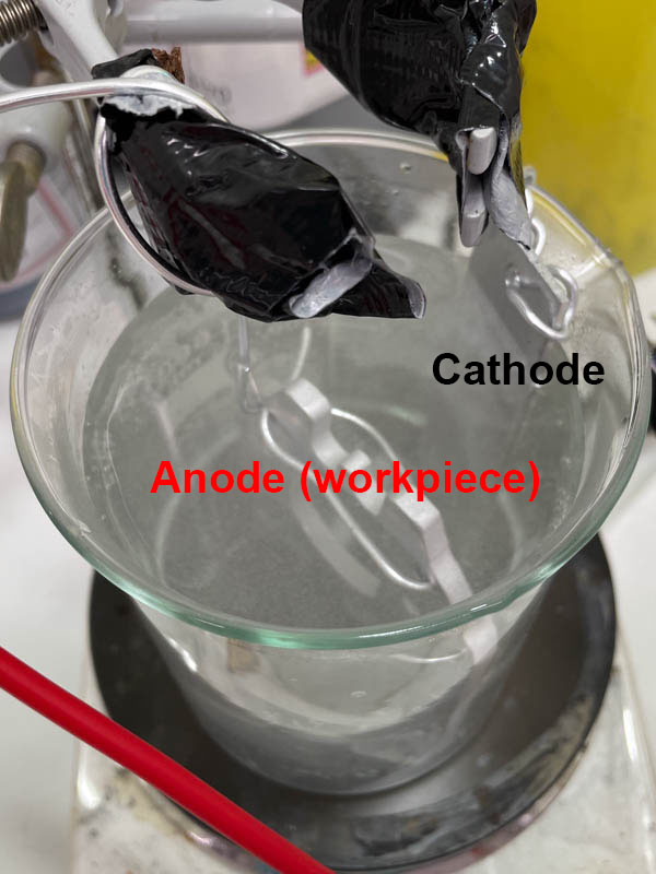
And now the anodization process can begin! The anodization bath is composed of a 18% w/w sulfuric acid solution: H2SO4 The process is done suspending the part in the bath by a strand of aluminum wire. This wire is attached to the positive side of the power supply (the workpiece is the anode) and an aluminum plate electrode is attached to the negative side (cathode). The common rule of thumb is to set the power supply to current-controlled mode and use 1.5 A per 100 cm2 of surface area. Conveniently, these parts were just about 100 cm2 and I used 1.5 A. One very important and annoying part about using aluminum wire to suspend the part, is that if the wire becomes momentarily disconnected (e.g. when moving the part), the wire itself may instantly anodize and then it loses a low-resistance path to the workpiece. You can tell this because the power supply will fail to supply the necessary current, or the voltage will go very high to maintain the current. For this reason I recommend to make sure the connection point is very tight! I let the anodizing process run from 30-40 min, rotating the part about half way through.
Dying (Optional)
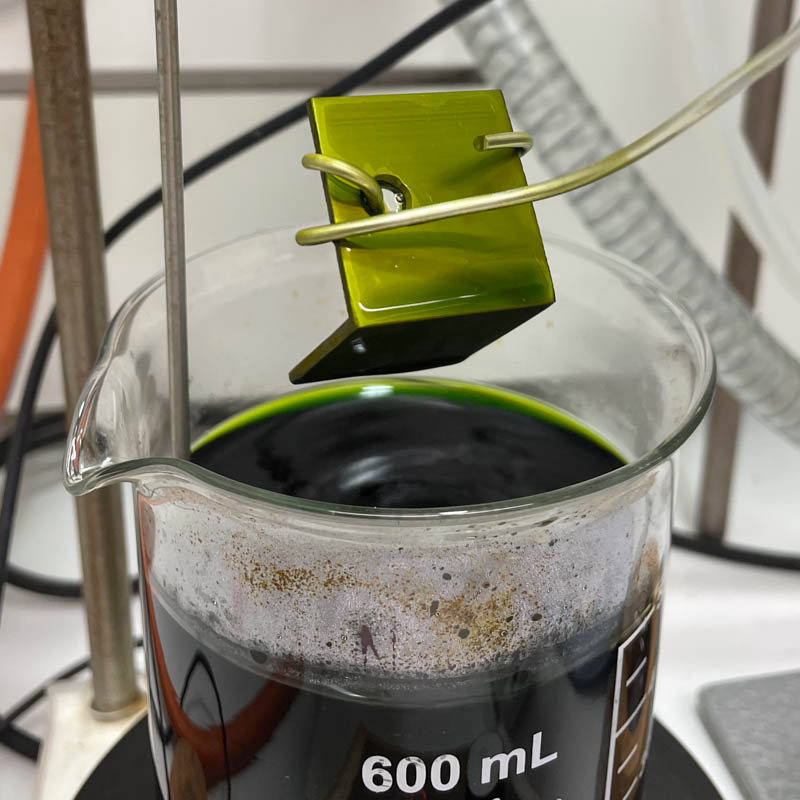
If desired, the parts can be dyed immediately after the anodization step. I purchased dyes from the excellent web store here, which also has many useful technical notes and instructions. I tried to replicate the green-gold colour anodization of the ATK FR14 by mixing 1 g/L chrome gold dye with 0.5 g/L of green dye. The result was not very close to the ATK colour, but it still left a good finish. Follow the dye manufacturer’s recommendations as they are all different, but for these, I immersed the parts for 2 min in the dye bath at 55°C. I also dyed some test pieces in this colour as well as the chrome yellow colour.
Sealing Step
The last step of the procedure is sealing, which is said to close the anodization surface pores and improve durability and colour retention. This is simple: the parts are boiled in distilled water for 1 hr.
Finished Product
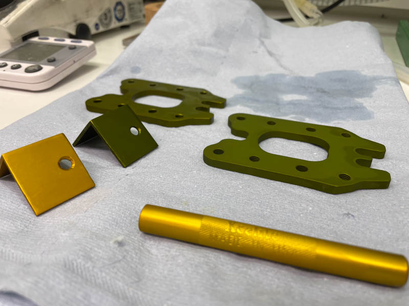
The anodized parts are shown here, along with the test pieces and an x-acto knife handle:
References
- Donahue, C. J., & Exline, J. A. (2014). Anodizing and coloring aluminum alloys. Journal of Chemical Education, 91(5), 711–715. https://doi.org/10.1021/ed3005598